Let There Be Movement!
EXAMINING CURTAIN WALL DEFLECTIONS
by Franz Safford, CEO and Founder of Innovation Glass. Posted on July 29, 2025.
“Let there be movement”—that sounds like a command from a deity! It is in fact an overwhelming attribute of our universe which is all about constant motion. In our world of building envelopes too, movement is a key parameter that compels evaluation to assure proper long-term performance.
It is critical that a facade system embrace all the possible wall distortions resulting from applied loads to assure that the weathering integrity of the curtain wall assembly is maintained through the full range and interactions of movements. It is equally important to properly define the deflection criteria, especially for long span facades, to assure that it does not create unintended higher costs of the completed facade. In this post I will discuss:
FACADE MOVEMENT BASICS
With its roots in the 1913 construction of the Fagus Shoe Last Factory [1] in Germany, a curtain wall today remains a “building skin” separate from the primary building structure. The curtain wall framing spans from slab edge to slab edge and is detailed to allow differential movements to occur between the building structure and the assembled curtain wall (referred to as “facade” hereafter). This is accomplished by integrating a fixed anchor (pin) and vertical slip anchor (slotted) in the local facade spans on a building. (The “local span” for instance is the span between any two floor slabs of a multi-story building).
What causes movements?
Applied forces (loads) and the effects of temperature changes result in distorting the theoretical shape of a facade. Primarily we discuss the “result” of the applied loads and thermal changes, which are “deflections.” Below are the movement sources that must be evaluated when designing a facade.
Wind loadsperpendicular to the facade surface
Wind creates perpendicular forces to the facade surface. The pressure force on the facade can be positive or negative (suction).
a. The overall building structure’s movements are considered as the facade is attached to it. Typically a buildings maximum movement (sway) is limited to L/400 where L = the building height.
b. When a building sways, as seen in Figure 1, each successive floor level is slightly offset from the one above/below. To accommodate it, facade details need to accommodate a value of ±3/4” of horizontal differential movement between anchor points. This value has become an industry standard and may be more than the actual lateral movements resulting from a building’s horizontal sway.
c. Wind loads cause facade deflections between anchor points, with the maximum deflection occurring at the mid way point between anchors. See blue overlay in Figure 1.
d. A building can also twist under wind load if it has a unique shape. These torsional overall movements and their effect on the local facade spans need to be considered as well if they are present on a project.
Dead loadof the floor slabs to which the facade is attached
a. The building structure irrespective of what material it is constructed will permanently deflect or bend under its own weight. See red overlay in Figure 2.
b. This will result in a shallow curved deflected shape of the edge of the floor slabs supporting the facade with the maximum deflection occurring at the center of the span between any two building columns.
c. Dead load deflection values can be obtained from the structural engineer of record for the building.
d. These types of deflections are typically accommodated by the facade by incorporating vertical adjustment capabilities into their anchor designs. This allows to facade anchors to be installed close to their theoretical positions which are necessary for a successfully facade construction.
Live load on the floor slabs to which the facade is attached
a. Transient or temporary loads on the floor slab of a building result in live load deflections. See green overlay in Figure 2.
b. These deflections are additive to the aforementioned dead load deflections and are typically limited to a maximum “net” value of L/600 or 3/8” between any two column spans.
c. At times larger live load deflections are associated with a building especially for existing construction being renovated. In such cases the facade detailing will have to be adjusted for the larger movements.
d. When installing a facade on a reinforced concrete building, creep needs to be considered. However due to the nature of concrete, typically by the time the facade is installed the building structure has already experienced ±90% of its creep (or column shortening) phenomenon, with long term creep effects well within the movement connections already incorporated into the facade detailing due to other movement issues.
SEISMIC EVENTS:ELASTIC AND INELASTIC MOVEMENTS
Both elastic and inelastic movements are considered in this analysis.
a. Elastic movements define the dynamic behavior of a building experiencing a seismic event (earthquake) during which the facade must accommodate the resulting movements without failing.
i. Elastic movements are typically in the same range of the building sway values due to wind loads or L/400 (L=building height).
ii. The facade must remain water and air tight during and after elastic movements.
b. Inelastic movements are those resulting from severe earthquakes during which the building structure undergoes permanent plastic deformation but does not collapse.
i. The facade has to be designed to survive the inelastic seismic event
ii. Common inelastic building movements are in the L/50 range (L=building height)
iii. The Design Team sets the survivability criteria for the facade (allowable glass breakage, seal failure, permanent frame deformation, etc…)
iv. Seismic events that cause inelastic deformations require the building to be demolished.
Thermal changesin the FACADE environment
a. This phenomenon (Figure 4) is technically not an applied load but it is an applied effect on a facade: materials contract and expand as the temperature changes.
b. Engineers typically evaluate the movement resulting from a facade experiencing a change from a cold temperature to one that is hot. Different jurisdictions will define different ranges based on local environmental conditions.
i. Key to this evaluation is to consider the thermal properties of different materials within the facade assembly to assure that their differential movements will not detrimentally affect wall performance over time.
c. Facade anchors are designed to accommodate the full range of thermal wall movements by incorporating slotted holes as required.
d. Notably most facades are at the interior of a building with a temperature controlled environment which limits large temperature swings. The effects of thermal changes therefore are of primary concern during the construction of the facade when it is in the open air or if the framing is exterior to the glass plane.
FACADE Self weight
When a curtain wall is inclined at an angle, the vertical component of the self weight (dead load) of the facade will cause it to permanently deflect between support points. See red overlay in Figure 5.
By considering the above mentioned sources of movement in facade detailing, long term weathering performance is assured.
Figure 1 · Wind Loads
Figure 2 · Dead Load & Live Load on the Floor Slabs
Figure 3 · Seismic Events
Figure 4 · Thermal Changes for a Ground-Based Facade
Figure 5 · Facade Self Weight
DEFLECTIONS: THE DESIGN TEAM HAS THE LAST WORD
Recognizing the movements that facades experience have to be managed to assure proper long term performance. Various codes define minimum limits for reference. These constraining values were derived mainly by considering the behavioral attributes of conventional curtain walls. We will discuss later in this post more about the different types of curtain wall technologies and how they react to movements.
It is important to note that the design team has the flexibility to define the deflection parameters that exceed those defined in the building codes. This freedom has permitted the development and implementation of exotic high deflecting glass walls such as cable nets.
CODE REQUIREMENTS DEFINING WALL MOVEMENTS
The following two standards define code minimums for facade deflections:
AAMA TIR-A11-04
a. L/175 for spans 13’-6” and under where “L” = the curtain wall clear span between supports
b. L/240+1/4” for spans between 13’-6” and up to 40ft
c. Maximum of ¾” across a glass lite
IBC section 1604.3 2018—which matches the AAMA document noted above
There are two key reasons facade deflections are limited.
Room partitions that abut the facade
Typically comprised of plaster board these walls are rigid and cannot absorb movement. The facade framing therefore needs to be designed stiff enough not to impact the interior walls and cause them to crack.
curtain wall System limitations
The waterproofing details of specific curtain wall systems require various levels of rigidity to prevent seals from failing under excessive movements. The aforementioned AAMA and IBC criteria speak well to the standard curtain wall system limitations for movement. If these standard systems are allowed to deflect beyond these values they are subject to failure allowing water to enter the building interior. Hence these criteria have become “industry standards” and are the default for facade specifications.
Therefore for the “every day” facade applications (10ft (3m) to 15ft (4.5m) wall heights) the AAMA TIR-A11-04 and IBC 1604.3 adequately define wall performance as it pertains to deflection structural behavior.
LONG SPAN FACADES
As already mentioned, most design and technical information guiding the design of facades is dedicated to the most commonly encountered building conditions, i.e., typical floor heights of ±10ft (3m) with maximum span limits for most curtain wall systems on the market world wide being 15ft (4.5m); typical vertical framing spacing = 4ft (1.2m) to 5ft (1.5m). With highly customized detailing, very deep mullions and extensive steel reinforcement, some standard facade systems can be modified to span up to ±20ft (6.0m) at a significant cost premium.
Long-span facades are therefore defined to be those that span more than 15ft (4.5m) to 20ft (6.0m). Because long-span facades typically occur in open spaces such as atriums, pre-function rooms and stadium entrances, the need to limit their deflection to prevent damage to interior partitions is eliminated. However, the system limitations of standard facades still exists which requires the addition of intermediate structure (back up steel), typically steel beams and columns are added behind the facade to provide lateral support at ±15ft o.c. over the total wall height. For example, a 60ft atrium wall would require three (3) horizontal beams to create 4, 15ft structural vertical bays. For long (wide) walls these beams require vertical columns to dissipate the facade loads to the primary building structure. If the original design program did not account for this secondary steel, the design goals of glass wall transparency are greatly compromised. See Figure 7 of a long span atrium hybrid point-supported (HPS) type of façade with no back up steel. Figure 6 shows the addition of steel beams and columns to provide support at 15ft. o.c. for a standard facade system. The visual impact of adding the structure is significant.
Figure 6 · 42ft high facade with two horizontal beams
Figure 7 · 42ft high clear span facade (HPS)
To achieve large clear spans for facades without the use of secondary steel, a number of facade strategies present themselves, which are listed below in order of cost effectiveness and complexity, with cable nets being on the highest end of both:
Hybrid Point-Supported (HPS) – clear spans to ±65ft (to-date; higher spans possible)
Aluminum extrusions (5” to 20” depth range)
Steel facades
Steel sections/built up members ±70ft (5” to 24” depth range)
Trusses ±150ft+ (typically span-to-depth of 1/15)
Shell structures (strength by geometry) ±100ft (structural depth 6” to 12”)
Tension based facades ±50ft+ (5” depth with tension cables at ±12ft o.c.)
For tall walls that with a width of 50ft to 80ft. wall height 150ft+
Glass Fin Walls
Cable nets ± 100ft (maximum span to-date is 400ft; structural depth = cable diameter; 1.5” to 5”)
design strategies for various curtain wall types

Figure 8 · Curtain Wall Maximum Deflection Criteria [2]
The Design Criteria for Long Span GLASS facades
Often on projects we see the specified deflection criteria for long-span walls being the boiler plate values for typical walls: L/175. To achieve that level of stiffness for a high spanning wall is of course possible by adding material and/or deepening the facade framing. This, however, significantly increases the cost of the facade. If the long-span facade is properly detailed (with 3rd party successful performance mock up (PMU) test reports) there literally is no benefit to the owner to pay the additional amount to make the facade deflect less for all the reasons noted herein. It is therefore prudent for the design community to define an appropriate long-span deflection criteria to achieve optimum value for the facade. See Figure 8 for a proven criteria that has been used for over 20 years in the US and internationally by Innovation Glass LLC for spans above 20ft.
Let’s examine a curtain wall with a clear span of 60ft. The maximum deflection at the half span location (30ft above the bottom anchor/floor) will be 8” if we use the L/90 criteria. This value at first glance appears shockingly high but it is important to acknowledge the meaning of this number:
1. It occurs 30 ft above the floor with zero deflection at the bottom of the wall.
2. It only occurs at maximum applied lateral load, when the wind is blowing at maximum speed.
Wind speeds being considered for today’s facades range from 90mph to 140mph+. Even with a changing climate, when was the last time anyone experienced those wind speeds outside of hurricane zones [3]? That maximum deflection value is only theoretically possible for a sustained maximum wind pressure. This is a critical point: too often the discussion during facade design development discusses this maximum deflection as if it were a value that can be expected to occur on a regular basis. When considering deflection criteria for a long spanning wall condition, it is more appropriate to examine what the “everyday” wind speeds are in any given jurisdiction to assess what the wall deflections may be on any given day.
Looking at Chicago, which is known as the windy city, monthly mean wind speeds over the past 30 years are in the range of 10 mph[4]. At that wind speed the wall movements are in the approximately ± ½”, 30ft above the floor. (At the bottom of the wall the deflection is zero because it is anchored to the building.) Hence the daily wall movements on a daily basis to a building occupant are imperceptible. This example noted the wind blowing at the 30 year mean speed value but on most days wind is typically only present in minor gusts so on most days the wall deflection will be zero.
We have the benefit of a number of built cable net and tension-based facades in the US and the world for over 25 years. These wall designs exhibit the highest deflection behavior of any wall type: L/50. For the 60ft clear span example above that converts to 14.4” 30ft above the floor at maximum sustained wind pressure. Even though this value is almost double the value of a framed facade (HPS or steel) the same argument applies: what are the everyday deflections?
Prominent completed cable net facades—UBS Tower at 1 N Wacker in Chicago, Deutsche Bank tower in NYC and the Kimmell Center in Philadelphia—have proven this out. When visiting these buildings on any given day, wall deflections are not detectable. I do however commend the boldness of the building owner of the New Poly Plaza in Beijing which has the largest cable net facade constructed to-date at 200ft x 400ft clear. The maximum deflection of that facade is 96” (8.0ft with a total pressure suction amplitude of 16ft). See Figures 9 and 10.

Figure 9 · New Poly Plaza, exterior · Photo: CC BY-SA 4.0
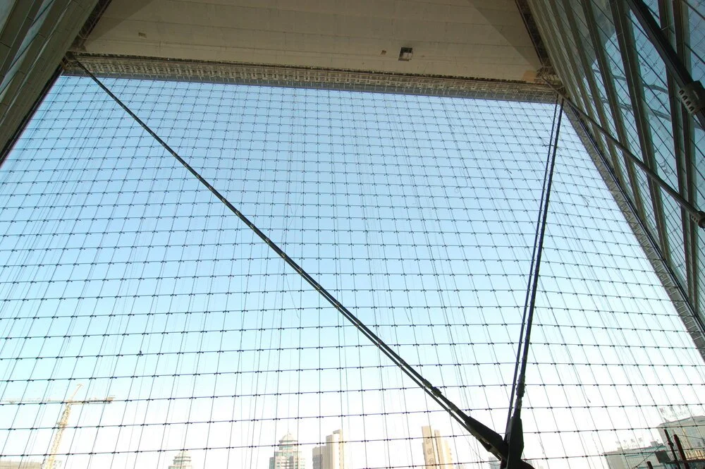
Figure 10 · New Poly Plaza, interior · Photo by Starq Design
Also of importance when defining the deflection criteria for long span facades is that if the typical short span criteria is forced onto long span facades a severe cost penalty is paid for the substantial increase in weight that is needed to achieve the increased wall stiffness. As noted in the commentary above, this added cost provides no added benefit to ownership and is, in essence, an avoidable waste of money.
Below are examples of various long span facade strategies.
Hybrid Point-Supported (HPS) curtain walls
The HPS technology was developed in the early 2000s. The leading system in this relatively new facade category is the VS1 system offered by Innovation Glass LLC. Figure 7 shows a 42ft clear span wall at the Adobe Utah Campus. Figure 11 is a HPS 45ft clear span at the University of Nebraska. Figure 12 showing a multi-story HPS facade with a maximum 42ft clear span and exterior mullion framing at the St. Regis Tower, Chicago.
HPS facades are comprised of one-way framing with no horizontal framing necessary; horizontal glass joints are flush 1” butt joints. The glass is offset from the face of the mullion by some 2” creating a planar visual expression of the glass which contributes to the lightness and high transparency characteristics of this facade approach. A direct glaze option is available which eliminates the 2” gap between the mullion and glass. The mullions are extruded aluminum and typically achieve the clear spans without steel reinforcing. The mullions are scaled to the spans and loads prevalent on the project.

Figure 11 · Osborne Legacy Center

Figure 12 · St. Regis Chicago
Figure 13 · Dominion Energy
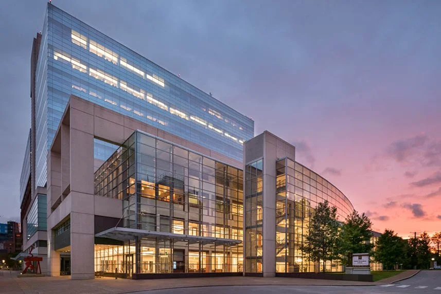
Figure 14 · Eskind Memorial Library

Figure 15 · John J. Moakley United States Courthouse
Steel facades
Steel sections either open or hollow are custom designed to achieve high span facades.
Figure 13 shows a large lobby atrium facade in Richmond, VA for Dominion Corp. comprised of 18” diameter HSS columns and 2” horizontal plate mullions spanning 30ft between columns.
Figure 14 shows a truss wall spanning 50ft at Vanderbilt University in Nashville, TN which was one of the first tension truss facades built in the United States in 1991 after the completion of the Louvre Pyramid in Paris.
STRESSed SHELL STRUCTURE
Figure 15 Shows a stressed shell structure at the courthouse in Boston, MA spanning 100ft with a structural depth of only 12”. The members are built up back to back channels to achieve sharp corners for the framing. Stainless steel tension rods developed the pre-tension in the structure to allow shell-action to dissipate the applied loads to the primary building structure.
Figure 16a · City Point Brooklyn
Figure 16b · Ryan Center at Northwestern U.
Tension cable curtain walls
These types of wall designs combine tension elements with framing to achieve an optimized approach to very transparent building envelopes. Typically the tension cables, which are prestressed to upwards of 60kips, are stretched horizontally at 10ft to 15ft and HPS framing is top hung between the cables. Notable is that the overall assembled wall deflects at the same level as a cable net, L/50. Detailing therefore has to embrace that movement which the HPS technology addresses well. Fig. 16a shows an 72ft high HPS tension based facade in NYC for City Point in Brooklyn. Figure 16b shows the Ryan Center at Northwestern University in Chicago.
CABLE NET FACADES
These structures are composed of two-way cables which are clamped together at the crossing points. Glass is corner supported and typically is monolithic; some cable net facades have been built with IGUs improving the thermal wall performance. Figures 9 and 10 show the largest cable net facade ever built. Figure 17 shows the first hypar cable net wall/roof built for the Security and Exchange Commission in Washington DC spanning 85ft [5].
Glass Fin Walls
These facades, first realized in the 1980s, utilize glass mullions or fins made from multiple tempered glass panels laminated together to create a structural vertical beam. Wall heights up to 80ft+ have been built to-date around the world. Recent enhancements in factory equipment allow unspliced fins up to 60ft (18.3m) to be implemented. When using low iron glass, this facade strategy can produce the most transparent end result of any option available. See Figure 18, which is a rendering of a large lobby wall in Dallas, Texas.
Figure 17 · Station Place

Figure 18 · 23Springs
CONCLUSION: DEFLECTION IN HIGH PERFORMANCE CURTAIN WALL SOLUTIONS
By applying rational thought and analysis to various wall conditions on buildings and developing appropriate details to accommodate the dynamic nature of building components and their performance, elegant, high performing facade solutions result that maximize value for owners and contribute to achieving excellent architecture.


Figure 19 · Fagus Shoe Last Factory
FOOTNOTES & SOURCES
[1] The Fagus Shoe Last Factory (Figure 19) is a UNESCO World Heritage Site in Alfeld, Germany, known, in part, as an early example of a curtain wall. Source: UNESCO World Heritage Commission. (A “last” is a mechanical form shaped like a human foot used by shoemakers when they repair shoes.) · Back↑
[2] The deflection criteria outlined in Figure 8 is for metal supported long-span facades. For glass fin walls, the standard deflection criteria noted on page 2 (AAMA TIR-A11-04 and IBC section 1604.3 2018 apply due to the more brittle nature of glass.) · Back↑
[3] Coastal zones in the US require high wind load criteria to be met by façade systems with Dade County, FL defining the most stringent requirements · Back↑
[4] Source: Wind and Window in the Windy City, Chicago Window Expert · Back↑
[5] A key attribute with cable net facades that significantly contributes to their high costs is the need for a substantially stiff boundary structure on all four sides. (Think of a giant tennis racquet.) Although mostly hidden this structure resists the high pre-stress loads which can be +/-60kips at 5ft o.c. around the perimeter. The cost of this boundary structure needs to be considered when evaluating cable net facade solutions to get a true wall cost estimate · Back↑
ABOUT THE AUTHOR
FRanz Safford, FACADE ENGINEER
CEO OF INNOVATION GLASS
Franz is an expert in all aspects of curtain wall construction process, from initial conception/design development, engineering, material selection, fabrication, project management and installation. He follows a process that strives for simplicity in the design solution, embracing a philosophy of integrating components to achieve a higher level of efficiency for the end-product. Read Full Bio →