Strategies for Managing Corner Zone Wind Pressure
HOW TO optimize curtain wall CORNER DESIGN for cost and AESTHETIC: “Don’t let the tail wag the dog.”
by Franz Safford, CEO and Founder of Innovation Glass
The design of corner conditions in architecture has its roots in 500BC when the Greeks created some of the most spectacular buildings ever conceived by mankind. They worked within the structural confines of stone and strove to achieve visual excellence at the highest level. This involved adjusting the building’s construction and components to correct the human eye’s characteristics in viewing rectilinear geometric forms (vanishing points).
Part of this process involved the corners of the buildings where the space between columns was reduced to counter the eye’s tendency to “correct” itself when viewing the end of a series of shapes (columns). By reducing the bay width of the corner columns, the facade appeared to have uniformly spaced columns. Had the aforementioned adjustment not been made, the last column bay would have appeared wider than the rest. The columns themselves were constructed gradually wider at mid-height (entasis) to make them appear as straight instead of slightly concave. In a further gesture to achieving visual perfection, the corner columns were made slightly wider in diameter to further correct the eye’s tendency to view and isolated shape as thinner than an array of the same shape. (See Fig. 1.)
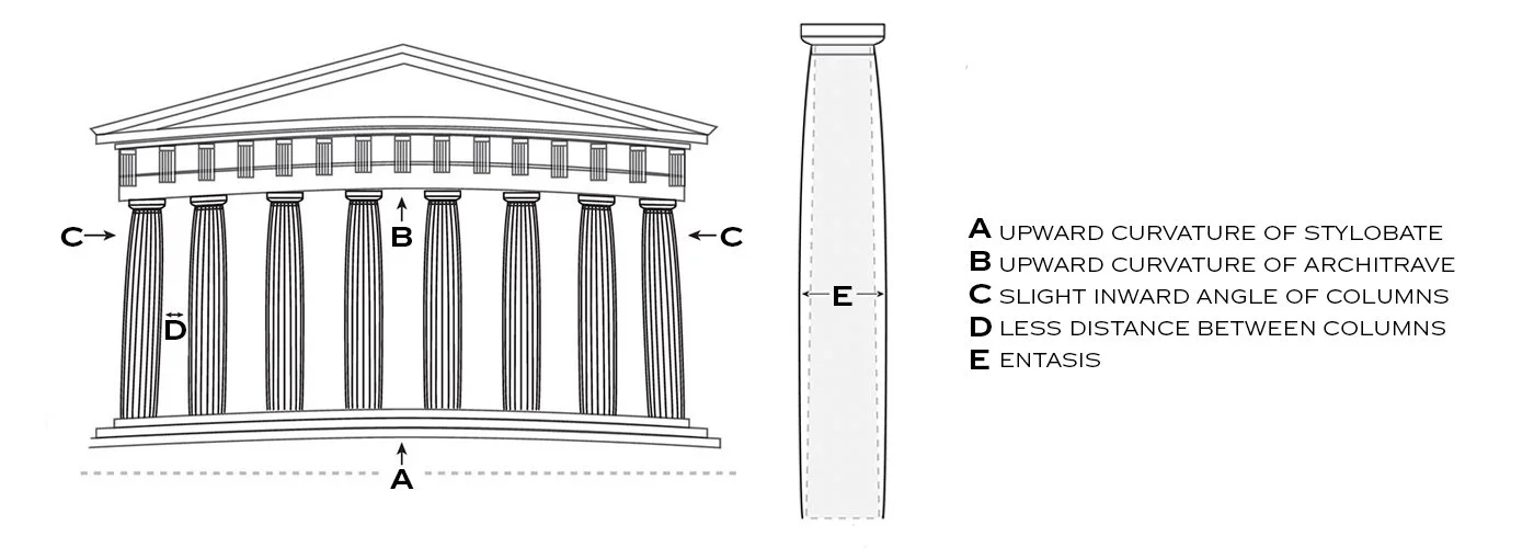
Figure 1 · Greek Temple
While the focus of Greek designers was aesthetic in perfecting the corner condition of their buildings, modern architects must also address another unique “corner condition” in their designs: higher wind pressures compared to the typical wall elevations. Today’s focus therefore is firstly performance-based but has aesthetic and important cost impacts as well.
In the absence of a subjective wind tunnel test, wind loads for projects in the US are derived from ASCE 7 which defines a wind pressure load amplifications at the corners. These higher values result from the increased fluid dynamic forces of air as it moves at a corner including the impact of vortices. For a typical medium sized, 50ft high building with a wind speed of 90mph, the typical design wind pressure = 17psf with a corner pressure of 21psf, a 23% increase.
Curtain wall design considerations for the corner zone
An initial tendency when sizing the glass and metal framing often is to use the higher corner zone loads only. However, this penalizes the majority of the curtain wall area with more metal and thicker glass, when comparing the case of the lower typical load values being used for the typical zones. This can significantly and unnecessarily increase the material cost of the curtain wall.
To prevent the “tail from wagging the dog” and to optimize curtain wall costs, it is suggested to evaluate the structural requirements of the curtain wall components in the typical zone (the majority of the wall area) and enhance the corner zone to accommodate the higher wind loads using one of the following approaches.
Add Aluminum Plates
This approach alleviates the glass over-deflecting due to wind at the VS1 standard unsupported horizontal edges, thereby avoiding thicker glass makeup requirements which would escalate the curtain wall unit cost.
a. These plates have a very narrow sightline (+/- 1/2”) and are visually minimized due their alignment with the horizontal joints. See photo in Fig. 2 of a completed glass corner using this approach. Fig. 3 has a detail section at the plate.
Figure 2 · Installed all-glass corner with concealed horizontal plates. M1 Bank in St. Louis→
Figure 3 · Detail at plate. Read more about VS1-A130→
Figure 4 · Moment base anchor
Moment connections at mullion anchors
By creating moment stiffness at one anchor the mullion deflection can be reduced to acceptable values.
a. Selecting the base anchor for the moment connection most often is the optimal approach due to its accessibility for the installer and that the base structure is usually reinforced concrete.
b. Coordination with the engineer of the building is key to allow the base building structure to be coordinated to resist the moment forces from the curtainwall anchors. This is imperative.
i. Typically this is achieved by adjusting the reinforcing steel design and the embed plates/bolts to which the anchors attach (weld).
c. The impact of the moment connection on the aluminum mullion section includes the evaluation of the combined stresses of bending (them moment) and axial loads if the wall is base loaded.
i. Consideration can be given to moving the moment connection to the top anchor if the moment connection overstresses the mullion section for a base loaded wall design. (See Fig. 4)
Add armatures
Excessive glass stresses and deflections can be eased by adding armatures to the corner mullions at the horizontal joints.
a. These fittings attach to the face of the mullion and features tapered ½” plates that provide intermediate lateral support for the horizontal glass edges. See Fig. 5 showing a plan view of an armature bracket as well as a photograph of an installation.
b. The armature brackets also blend at distance due to their alignment with the horizontal joints. The end fittings can be painted black or a concealed toggle fitting can be used to hold the glass, eliminating the patches.
Figure 5 · VS1 armature detail
Figure 6 · Installed facade corner with armatures.

Figure 7 · Montserrat Chapel at Creighton University
Adjust the glass bay width
Glass stress and edge deflection can be reduced by paring back glass sizes and tributary area of the mullion.
a. This strategy most strongly visually communicates that something unique is occurring at the corner and the facade geometry is responding to it. If done appropriately, visually the elevation can achieve similar results to those intended by the Greek designers. (See dimension D of Fig. 1.)
b. No additional brackets or plates are needed to achieve glass stress and deflection reductions
c. For larger corner zones the glass bays can be stepped down to a desired width based on structural calculations. See Fig. 7 for a graphic markup of an existing project.
INTERNAL mullion reinforcement
Finally, this strategy addresses excessive mullion deflections for very high wind pressure conditions by inserting a steel plate into the mullion cavity. By using a reasonable approach to deflections however, this approach is rarely needed with the VS1 technology. (See our recent blog post “Let there be Movement.”)
ELEGANT FACADE SOLUTIONS
By embracing the unique aspects of what occurs at the corners of glass curtain walls and addressing them in a purposeful manner, a facade designer can achieve an elegant facade solution at best value for the owner.

ABOUT THE AUTHOR
FRanz Safford, FACADE ENGINEER
CEO OF INNOVATION GLASS
Franz is an expert in all aspects of curtain wall construction process, from initial conception/design development, engineering, material selection, fabrication, project management and installation. He follows a process that strives for simplicity in the design solution, embracing a philosophy of integrating components to achieve a higher level of efficiency for the end-product. Read Full Bio →
Read More
Explore recent posts below to learn more about Innovation Glass and the VS1 technology.